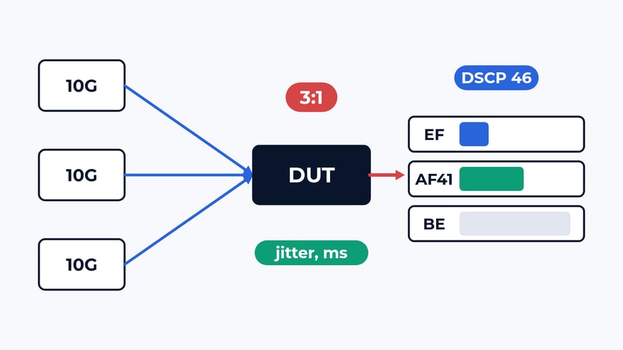
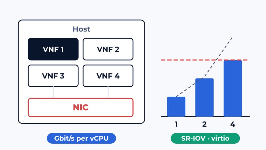
A leased Ethernet circuit arrives with a contract and a turn-up sheet. The contract names a CIR per service, delay, loss and availability, for example 99.95%. The sheet says "passed" after one full-rate run or a ping, which does not show whether voice, video and data each get their CIR when all 3 run at once, whether the policer cuts at the right line, and whether the delay on the operator's portal is the delay your traffic sees. We answer these 3 questions for the operator handing the circuit over and for the customer signing the acceptance.
The bench
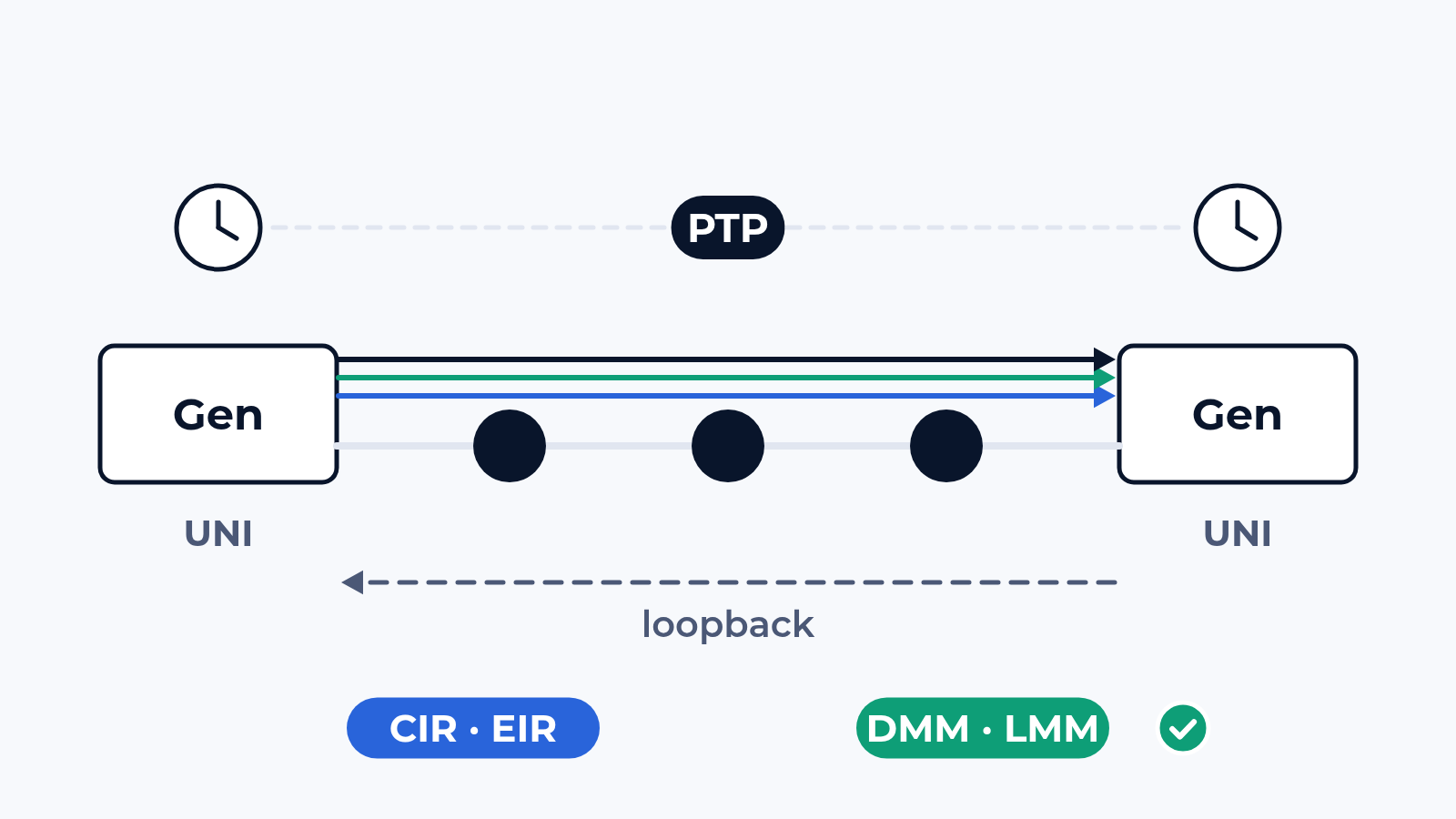
The generator sends one stream per service with its VLAN and marking, a sequence number and a timestamp in every frame. At the far end, a loopback with MAC swap is enough for rate, loss and round-trip delay. One-way delay and jitter need a second generator unit on a common clock from GPS or PTP. Our generators emulate PTP; a full analysis of the sync itself is a separate item agreed per project. Ports are 1G, 10G and 100G, 400G and faster per project.
We work on the CloudLAB bench with your device, or on your circuit with our units at both ends. For OAM the generator plays the peer MEPs: CCM at the agreed interval, DMM and LMM at the service priority. A WAN emulator adds a known delay and a known loss, so each OAM figure has a reference.
What we check
- Y.1564 configuration test, service by service: 25, 50, 75 and 100% of CIR, then CIR + EIR, then 25% above that to prove the policer; IR, FTD, FDV and FLR at every step
- Frame colour: green frames within CIR must arrive without loss, yellow frames above it may be dropped and are counted apart; CBS and EBS bursts when the SLA names them
- Performance test: all services at their CIR together for 15 minutes, 2 hours or 24 hours, every metric per service per second
- Y.1731 continuity: CCM at 3.3 ms or 100 ms, a link cut under traffic, the time to loss of continuity on the wire (the limit is 3.5 intervals) and RDI at the peer
- Delay: two-way DMM/DMR and one-way 1DM at 0, 40, 80 and 95% background load, each figure next to the generator's own measurement on service frames in the same second
- Loss: LMM/LMR on the service counters and SLM/SLR on synthetic frames, the emulator dropping a known 0.1%, then 1%
- Faults across levels: loopback and linktrace per MIP, AIS from the operator level to the customer level, 2 vendors on one MEG
What usually breaks
Services that pass alone and fail together. A typical case: a 1 GbE UNI with voice, video and data, every configuration step clean. In the performance test, from the 38th minute, the data service loses 0.42% of its green frames. The 3 CIRs add up to 620 Mbit/s, while the policer on an aggregation node is set to 450 Mbit/s, a figure from an earlier version of the order. One service never reaches that line. All 3 together do.
A portal that is right on an idle port. Without load a demarcation device reports 0.21 ms, the generator measures 0.20. At 80% load the device still reports 0.8 ms, the generator 4.1 ms on the service frames. The DMM frames went at PCP 7, the service at PCP 3, so OAM skipped the queue the customer was waiting in. One line of configuration, a rerun: 4.0 ms against 4.1.
Round trip divided by 2. A loopback gives the round-trip delay, and the turn-up sheet halves it. When the 2 directions take different paths or carry different load, half of the round trip matches neither of them. If the SLA quotes one-way delay or jitter, the plan puts a second unit with a common clock at the far end.
What is in the report
A pass or a fail per service and per metric: IR offered against received at every step, green and yellow counts, FTD and FDV as min, average and max, FLR and available seconds. For OAM: the detection time per link cut, DM and LM from the device next to the reference at each load step, missed CCMs. One-second series as CSV and raw counters from both ends. The operator and the customer get one report and read the same numbers.
Where to start
Send us the service table or the SLA extract, the devices at both ends and the circuit topology. We answer with a draft test plan: the items, the bench layout and the dates. The report is yours to keep and to show to the provider or the vendor. Write to us or look at what else the bench does.
 Alexander Zemskov
5 min read
 Alexander Zemskov
4 min read